2) Valve Selection Criteria - (1) Valve Coefficients and Three Principal Types of Flow Type
Engineering - Valves ·When you design the pneumatic or hydraulic system, according to the Bernoulli’s equation in compressible flow situation
where $g$ is the gravity acceleration constant, $h$ is the height of the fluid line from the reference point, $\rho$ is the density property of fluid being analyzed, and $\int dP$ is the pressure drop within the measurement time scope. Above term is the mechanical energy of the fluid per unit mass. There are the constraints to use the Bernoulli’s equations, which are:
- Steady Flow
- Negligible Viscous Effects
- No Shaft Work
- Incompressible Flow
- Negligible Heat Transfer
- Flow along a streamline
These things are considered deeply in Fluid Mechanics sections, so these are skipped in this time. Usually the closure element, such as a plug or a disk, is located just off the seat, which leads to the possibility of creating a high pressure drop and faster velocities—causing cavitation, flashing, or erosion of the trim parts. In addition, if the closure element is closure to the seat and the operator is not strong enough to hold that position, it may be sucked into the seat. This problem is appropriately called the bathtub stopper effect. That’s why we have to focus in the $\int dP$.
In many occasion, we can approximate the $\int dP$ into $\Delta P$. As we can see in $(2.1)$, the pressure drop is very important when you design the pneumatic or hydraulic system, because velocity of the fluid varies with the pressure drop by the valve structure(installed flow characteristic), regardless of whether the height difference could be ignored (height can be measured easily). Considering that, the valve coefficients are to evaluate the performance of the valve according to the pressure drop.
where $C_v\,=\,$ required flow coefficient for the valve
$Q\,=$ flow rate [gal/min]
$S_g\,=$ specific gravity of the fluid
$\Delta P\,=$ pressure drop [psi]
when you design the pneumatic or hydraulic system, you would often design with the Imperial units, so we should be used to take the imperial units system.
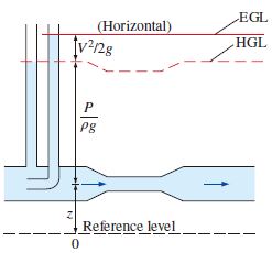
Let use the HGL(Hydraulic Grade Line) and EGL(Energy Grade Line) to visualize the Bernoulli’s equation much easier to understand $(2.2)$. To do this, Divide $(2.1)$ by $g$. Then we can evaluate
in this case, HGL is the $\frac{P}{\rho g}+h$(Pressure Head and Elevation Head), and EGL is HGL + $\frac{V^2}{2g}$, so $(2.3)$ is the formula of EGL. Let me show you some of explanation:
- For stationary bodies such as reservoirs or lakes, the EGL and HGL coincide with the free surface of the liquid. The elevation of the free surface z in such cases represents both the EGL and the HGL since the velocity is zero and the static (gage) pressure is zero.
- The EGL is always a distance $V^2/2g$ above the HGL. These two curves approach each other as the velocity decreases, and they diverge as the velocity increases. The height of the HGL decreases as the velocity increases, and vice versa.
- In an idealized Bernoulli-type flow, EGL is horizontal and its height remains constant. This would also be the case for HGL when the flow velocity is constant. [Fig. 2.1].
- For open-channel flow, the HGL coincides with the free surface of the liquid, and the EGL is a distance V2/2g above the free surface.
- At a pipe exit, the pressure head is zero (atmospheric pressure) and thus the HGL coincides with the pipe outlet [location 3 on Fig. 2.2.]
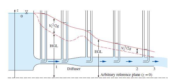
- The mechanical energy loss due to frictional effects (conversion to thermal energy) causes the EGL and HGL to slope downward in the direction of flow. The slope is a measure of the head loss in the pipe. A component that generates significant frictional effects such as a valve causes a sudden drop in both EGL and HGL at that location.
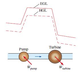
- A steep jump occurs in EGL and HGL whenever mechanical energy is added to the fluid (by a pump, for example). Likewise, a steep drop occurs in EGL and HGL whenever mechanical energy is removed from the fluid (by a turbine, for example), as shown in [Fig. 2.3.].
- The gage pressure of a fluid is zero at locations where the HGL intersects the fluid. The pressure in a flow section that lies above the HGL is negative, and the pressure in a section that lies below the HGL is positive. Therefore, an accurate drawing of a piping system overlaid with the HGL can be used to determine the regions where the gage pressure in the pipe is negative (below atmospheric pressure).
By these statements and explanations for EGL and HGL, we find the velocity out approximately. Basically this kind of measurement is to find out what the pressure difference is. In industrial situation(in case that the working fluid is hydraulic fluid), generally flow is steady [Steady Flow], and density change can be negligible [Incompressible Flow]. Other conditions can be different, but in fundamental viewpoint, individual valve and piping subsystem can satisfy above six condition often, so simple analysis with the Bernoulli’s equation can work.
Inherent flow characteristic: The characteristics when a valve is operating with a constant pressure drop without taking into account the effects of piping.
Installed flow characteristic: The characteristics when both the valve and piping effects are taken into account. In this time, the flow characteristic changes from the ideal curve.
The characteristic cage and linear plugs are below:
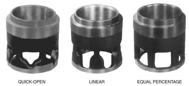
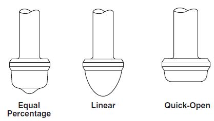
-
Equal-Percentage Flow Characteristic
With an equal-percentage characteristic, the change in flow per unit of valve stroke is directly proportional to the flow occurring just before the change is made. In formula,
$\frac{dQ}{dL}=nQ,\, Q=Q_0 e^{nL}$
where $Q$: Flow rate, $L$: Valve travel, $e$: $\underset{k \rightarrow \infty}{\lim}{(1+\frac{1}{k})}^k≒2.7181$, $Q_0$: minimum controllable flow, $n$: constant.
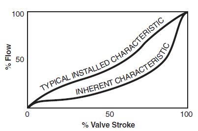
Fig. 2.7. Typical inherent and installed equal-percentage flow characteristics. -
Linear Flow Characteristic
The inherent linear flow characteristic produces equal changes in flow per unit of valve stroke, regardless of the position of the valve. For the most part, linear flow characteristics provide better flow capacity throughout the entire stroke, as opposed to equal-percentage characteristics. In formula,
$\frac{dQ}{dL}=k,\, Q=kL$
Where $k$: constant of proportionality.
-
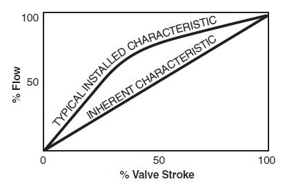
Quick-Open Flow Characteristic
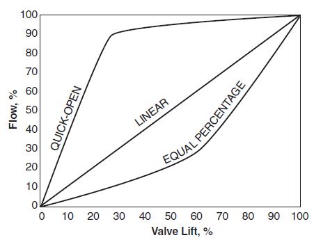
The quick-open characteristic is used almost exclusively for on–off applications, where maximum flow is produced immediately as the valve begins to open. Because of the extreme nature of the quick-open characteristic, the inherent and installed characteristics are similar.
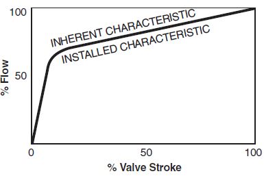
Fig. 2.9. Typical inherent and installed quick-open characteristics.
We’ve studied the concepts and fundamentals of the valve coefficients, and the principal three types of valve flowing. Valve coefficients are to define the performance of valve system according to the pressure drop. Three types of the flow characteristics are Equal-Percentage Flow Characteristic, Linear Flow Characteristic, and Quick-Open Flow Characteristic, and the plot of flow percentage according to the valve stroke percentage is [Fig. 2.4.].
We didn’t see much about the inherent flow characteristics and installed flow characteristics, so in the next article, we’ll see about that.
- References
- Valve Handbook, 2nd ed., p.1.
- Yunus A. Cengel, 4th Ed., Fluid Mechanics - Fundamentals and Applications