4) Axial Load
Engineering - Mechanics of Materials ·We have shown that the mathematical relationship between stress and strain depends on the type of material from which the body is made. In particular, if the material behaves in a linear elastic manner, then Hooke’s law applies, and there is a proportional relationship between stress and strain. Using this idea, consider the manner in which a rectangular bar will deform elastically when the bar is subjected to the force P applied along its centroidal axis, [Fig. 4.1].
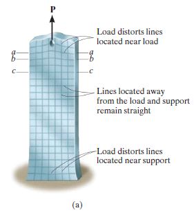
If the material remains elastic, then the strains caused by this deformation are directly related to the stress in the bar through Hooke’s law, $\sigma = E\epsilon$. As a result, a profile of the variation of the stress distribution acting at sections a–a, b–b, and c–c, will look like that shown in [Fig. 4.2.].
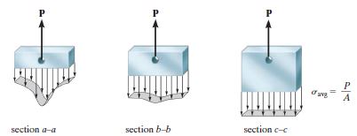
By comparison, the stress tends to reach a uniform value at section c–c, which is sufficiently removed from the end since the localized deformation caused by P vanishes. The minimum distance from the bar’s end where this occurs can be determined using a mathematical analysis based on the theory of elasticity. It has been found that this distance should at least be equal to the largest dimension of the loaded cross section. (It would be stated in the theory of elasticity in detail.) Hence, section c–c should be located at a distance at least equal to the width (not the thickness) of the bar, and our interests are almost in this region, c-c. This fact is Te Saint-Venant’s Principle.
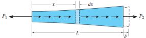
Think about the general situation of elastic deformation. What we want to know is $\delta$, the infinitesimal length changed by $P_1$ and $P_2$. But wait, how can we find $P_1$ and $P_2$? To make this difficulty up, we get a infinitesimal element.
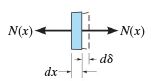
The resultant internal axial force will be a function of x since the external distributed loading will cause it to vary along the length of the bar. Now we take $P_1$ and $P_2$ place with $N(x)$, and then from this we can start.
When the stress doesn’t exceed the elastic limit, we can apply the Hooke’s law: $\sigma = E(x) \epsilon$, and by this we can obtain
In constant load and cross-sectional area situation, which is the ‘Engineering Situation’ as we’ve seen in ‘conventional stress-strain curve’, we can take $N(x),\,A(x),\,E(x)$ as all constant. Then, (4.1.) is to be
When the material is elongated, sign is (+), otherwise (-). This is the sign convention about the axial deformation. As we assumed that we analyze the deformation in c-c region, which means that the deformation is linear when the material is not in the plastic deformation region, we can apply the principle of superposition. The following two conditions must be satisfied if the principle of superposition is to be applied.
- The loading $N$ must be linearly related to the stress $\sigma$ or displacement $\delta$ that is to be determined. For example, the equations $\sigma = \frac{N}{A}$ and $\delta = \frac{NL}{AE}$ involve a linear relationship between $\sigma$ and $N$, and $\delta$ and $N$.
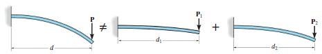
- The loading must not significantly change the original geometry or configuration of the member. If significant changes do occur, the direction and location of the applied forces and their moment arms will change. For example, consider the slender rod shown in [Fig. 4.5.], which is subjected to the load $\mathbf{P}$. In [Fig. 4.5.], $\mathbf{P}$ is replaced by two of its components, $\mathbf{P} = \mathbf{P_1} + \mathbf{P_2}$. If $\mathbf{P}$ causes the rod to deflect a large amount, as shown, the moment of this load about its support, $Pd$, will not equal the sum of the moments of its component loads, $Pd \neq P_1d_1 + P_2d_2$, because $d_1 \neq d_2 \neq d$.
Remember the statics class? At that time, we took the redundant force off to find out the force acting on the certain support. Now we have to take advantage of the redundant forces to find out what the deformation of the material actually is when the equations of equilibrium are not sufficient to determine all the reactions on a member. In this time, commonly the compatibility conditions specify the displacement constraints that occur at the supports or other points on a member. Consider a example to explain the case we have to apply the compatibility to statically indeterminate problem.
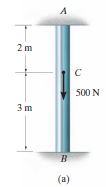
How to find the force acting on A and B when 500N is acting on C downward? We take the information from picture that and , so let’s get start with this. using a load–displacement relationship, which depends on the material behavior, we can find out the internal force in segment $AC$ is $+F_A$, and in segment $CB$ it is $-F_B$. Again, $\delta_{A/B} = 0$, which means that
By this, we can get $F_A = 300N\text{ and }F_B = 200N$.
This method of solution, which can make us solve statically indeterminate problems by writing the compatibility equation using the principle of superposition, is often referred to as the flexibility or force method of analysis. The procedure for the analysis includes these kind of steps:
Compatibility.
- Choose one of the supports as redundant and write the equation of compatibility. To do this, the known displacement at the redundant support, which is usually zero, is equated to the displacement at the support caused only by the external loads acting on the member plus (vectorially) the displacement at this support caused only by the redundant reaction acting on the member
Load–Displacement.
-
Express the external load and redundant displacements in terms of the loadings by using a load–displacement relationship, such as $\delta = \frac{NL}{AE}$.
-
Once established, the compatibility equation can then be solved for the magnitude of the redundant force.
Equilibrium.
- Draw a free-body diagram and write the appropriate equations of equilibrium for the member using the calculated result for the redundant. Solve these equations for the other reactions.
- Thermal Stress: A change in temperature can cause a body to change its dimensions. Generally, if the temperature increases, the body will expand, whereas if the temperature decreases, it will contract. (1) If this is the case, (2) and the material is homogeneous and isotropic, it has been found from experiment that the displacement of the end of a member having a length L can be calculated using the formula
-
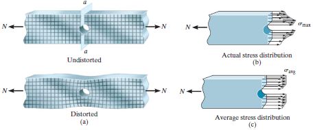
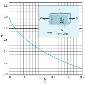
Stress Concentrations: As we’ve seen on the [Fig. 4.1.], [Fig. 4.7.] states the concentration effect for the local region such as hole, crack, etc.. Consider, for example, the bar in [Fig. 4.7.a], which is subjected to an axial force N.
Here the once horizontal and vertical grid lines deflect into an irregular pattern around the hole centered in the bar. The maximum normal stress in the bar occurs on section a–a, since it is located at the bar’s smallest cross-sectional area. Provided the material behaves in a linear elastic manner, the stress distribution acting on this section can be determined either from a mathematical analysis, using the theory of elasticity, or experimentally by measuring the strain normal to section a–a and then calculating the stress using Hooke’s law, .
If instead the bar has a reduction in its cross section, using shoulder fillets as in [Fig. 4.8.a], then at the smallest cross-sectional area, section a–a, the stress distribution will look like that shown in [Fig. 4.8.b].
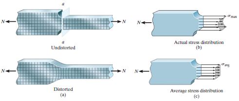
In both of these cases, force equilibrium requires the magnitude of the resultant force developed by the stress distribution at section a–a to be equal to $N$. In other words,
In engineering practice, above integral is hard to be defined and calculated. Instead, we have the set of the values and graph of the stress concentration factor $K$ such that $K = \frac{\sigma_{\text{max}}}{\sigma_{\text{avg}}}$.
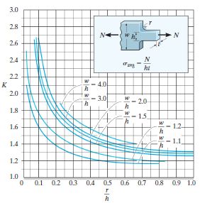
Using this table, we get the upper limit for the engineering design for each cases,
-
Inelastic Axial Deformation: If the loading on a bar made of ductile material causes the material to yield, then the stress distribution that is produced can be determined from the strain distribution and the stress–strain diagram. Assuming the material is perfectly plastic, yielding will cause the stress distribution at the cross section of a hole or transition to even out and become uniform. At the complete plastic deformation phase, the plastic load $N_p$ is
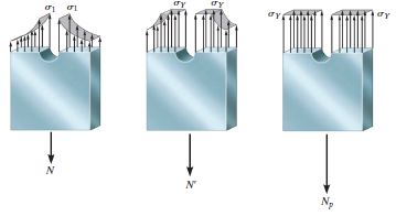
4.11. The Time when The Plastic Deformation Occurs Firstly, $\sigma_1$ reaches to the yielding normal stress of certain material, $\sigma_Y$, which is same to the [Fig.4.11.]’s left diagram. Then stress distribution goes to the middle of [Fig.4.11.]. As we can see, the maximum value of the stress distribution cannot exceed the yielding stress of the material. Finally, all continuous value of stress distribution arrive at the yielding stress.
-
Residual Stress:
Consider a prismatic member made of an elastoplastic material having the stress–strain diagram shown in [Fig. 4.12.].
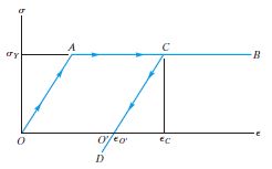
4.12. The Stress-Strain Diagram when The Material Undergoes The Residual Stress If an axial load produces a stress $\sigma_Y$ in the material and a corresponding strain $\epsilon_C$, then when the load is removed, the material will respond elastically and follow the line $CD$ in order to recover some of the strain. A recovery to zero stress at point $O’$ will be possible if the member is statically determinate, since then the support reactions for the member will be zero when the load is removed.
Under these circumstances the member will be permanently deformed so that the permanent set or strain in the member is $PO’$. If the member is statically indeterminate, however, removal of the external load will cause the support forces to respond to the elastic recovery CD. Since these forces will constrain the member from full recovery, they will induce residual stresses in the member.
To solve this kind of problems, the complete cycle of loading and then unloading of the member can be considered as the superposition of a positive load (loading) on a negative load (unloading).
Now we’ve seen how to solve the problem when the axial load alone is exerted on the member. We have to see the ‘Torsion’, ‘Bending’, ‘Transverse Shear’ more, and finally we have to combine them all. Although there are a lot of things to have to be studied, applying the old saying: ‘divide and conquer’, and we can get this all out.
- References
- R.C. Hibbeler, “Mechanics of materials”, Pearson, 10th ed., ch.4
- Ferdinand P. Beer, Mechanics of Materials, 5th ed., ch.2