3) Mechanical Properties of Materials - From The Ductility and Brittleness
Engineering - Mechanics of Materials ·Ductile Materials: Any material that can be subjected to large strains before it fractures is called a ductile material. Mild steel, as discussed previously, is a typical example. Engineers often choose ductile materials for design because these materials are capable of absorbing shock or energy, and if they become overloaded, they will usually exhibit large deformation before failing.
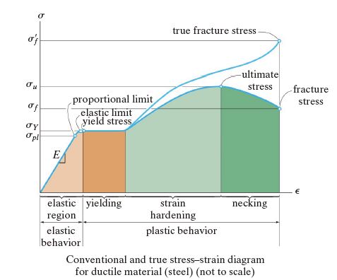
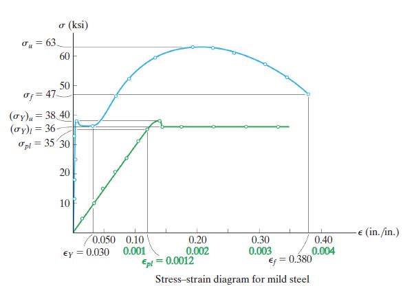
Recalling the stress-strain diagram, $\sigma _Y \text{(Yielding Stress)}$ can be found at [elastic limit yield stress] in above figure. The meaning of the $\sigma _Y$ is that the starting point of plastic deformation. Ductile material passes this point certainly. Through this point and when the ductile material is about to be necking, $\sigma _u \text{(Ultimate Stress)}$ the upper limit of the conventional stress-strain diagram. Realize that the yield strength is not a physical property of the material, since it is a stress that causes a specified permanent strain in the material. In this text, however, we will assume that the yield strength, yield point, elastic limit, and proportional limit all coincide unless otherwise stated.
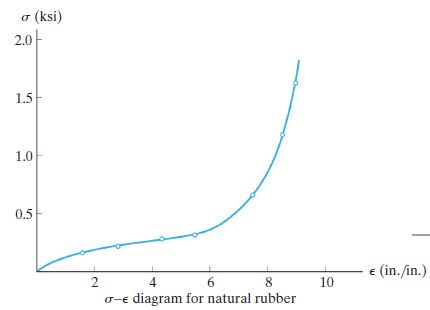
An exception would be natural rubber, which in fact does not even have a proportional limit, since stress and strain are not linearly related. Instead, as shown in [Fig. 3.1.] this material, which is known as a polymer, exhibits nonlinear elastic behavior.
Brittle Materials: Materials that exhibit little or no yielding before failure are referred to as brittle materials. Gray cast iron is an example, having a stress–strain diagram in tension as shown by the curve AB in [Fig. 3.2.]
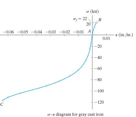
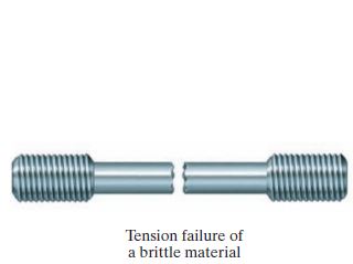
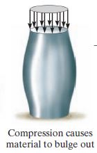
Brittle Material doesn’t undergo the yielding, and it goes to the fracture directly. Since the appearance of initial cracks in a specimen is quite random, brittle materials do not have a well-defined tensile fracture stress. Instead the average fracture stress from a set of observed tests is generally reported. A typical tensile and compressive failure is stated on [Fig. 3.3] and [Fig. 3.4.] below.
If the material has a well-defined yield point as in [Fig. 3.5], the elastic limit, the proportional limit, and the yield point are essentially equal. In other words, the material behaves elastically and linearly as long as the stress is kept below the yield point.
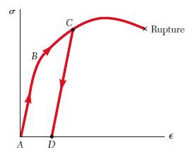
However, if the yield point is reached, The plastic strain remains, and as a result the material will be subjected to a permanent set. It is a kind of a hysteresis, which means that the system is not independent to the process path. When the load is removed, the stress and strain decrease in a linear fashion along a line CD parallel to the straight-line portion AB of the loading curve [Fig. 3.6]. We says this process as strain hardening.
If, after being loaded and unloaded [Fig. 3.7.], the test specimen is loaded again, the new loading curve will follow the earlier unloading curve until it almost reaches point C. Then it will bend to the right and connect with the curved portion of the original stress-strain diagram. Then it will bend to the right and connect with the curved portion of the original stress-strain diagram.
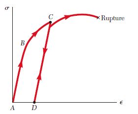
In abstract, in stress-strain diagram, if the stress acting on a material is below yielding stress, the material behaves elastically and linearly when the exerted stress is below the yielding stress. Exceeding the yielding stress, elastic region starts from D in [Fig. 3.7] Elastic behavior represents which the material is getting recovered below the yielding stress region. If not, it is the plastic behavior.
Before stating the above subjects, we need to know that there are several kinds of loading: Axial loading, radial loading, thermal loading, and other corrosive processing that can make some changes for the material itself. To prevent the aging of the component and structure which composed of several materials, many kinds of surface engineering is applied to the processing, but even if they're done, the permanent damage cannot be undone.
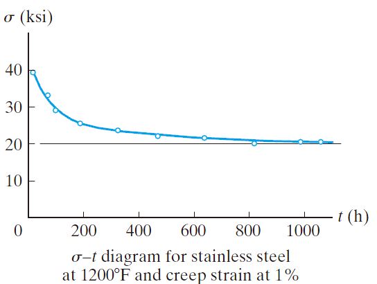
Creep: When a material has to support a load for a very long period of time, it may continue to deform until a sudden fracture occurs or its usefulness is impaired. This time-dependent permanent deformation is known as creep. This is due to the long-period static loading, and normally(except the polymers and composite materials - in this case, temperature is not an important factor)including thermal loading as the support of some structure.
For practical purposes, when creep becomes important, a member is usually designed to resist a specified creep strain for a given period of time. An important mechanical property that is used in this regard is called the creep strength. This value represents the highest stress the material can withstand during a specified time without exceeding an allowable creep strain. The creep strength will vary with temperature, and for design, a temperature, duration of loading, and allowable creep strain must all be specified. For example, a creep strain of 0.1% per year has been suggested for steel used for bolts and piping.
Fatigue: When an cyclic loading is exerted onto the material, internal structure of material goes to get broken down, and it leads to the fracture. This phenomena is called to fatigue, and this phenomena is shown many time in connecting rods and crankshafts of engines; steam or gas turbine blades; connections or supports for bridges, railroad wheels, and axles; and other parts subjected to cyclic loading, as the components or structures undergo the dynamic loading. In all these cases, fracture will occur at a stress that is less than the material’s yield stress.
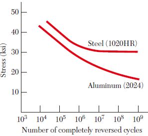
A typical $\sigma - n\text{(cycle number)}$ curve for steel is shown in [Fig. 3.9.] If the applied maximum stress is high, relatively few cycles are required to cause rupture. As the magnitude of the maximum stress is reduced, the number of cycles required to cause rupture increases, until the endurance limit is reached. The endurance limit is the stress for which failure does not occur, even for an indefinitely large number of loading cycles. For a low-carbon steel, such as structural steel, the endurance limit is about one-half of the ultimate strength of the steel.
For nonferrous metals, such as aluminum and copper, a typical $\sigma - n$ curve [Fig. 3.9] shows that the stress at failure continues to decrease as the number of loading cycles is increased. For such metals, the fatigue limit is the stress corresponding to failure after a specified number of loading cycles.
For now, we discovered the ductility and brittleness, elastic and non-elastic behavior, and the creep and the fatigue. These are the basic knowledge for preceding several analysis - The most important part of the mechanics of materials -. The several methods how to determine the creep strength and fatigue strength is not for today. In the material science, these are to be dig deeply.
- References
- R.C. Hibbeler, “Mechanics of materials”, Pearson, 10th ed., ch.3
- Ferdinand P. Beer, Mechanics of Materials, 5th ed., ch.2