2) Stress and Strain - Strain
Engineering - Mechanics of Materials ·When an excessive stress is applied to the body of certain material, the shape of the body would be changed. It is called to Deformation. The deformation includes the case of yielding, necking, and rupture, etc., but in this chapter yielding is the principal subject. In a general sense, the deformation will not be uniform throughout the body, and so the change in geometry of any line segment within the body may vary substantially along its length. So, normally the deformation is measured for a small specimen of a certain material.
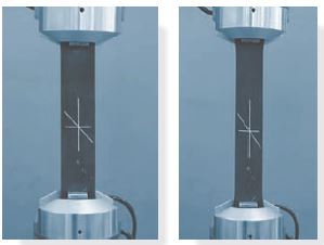
But also one can realize that the deformation depends on the orientation of the specimen at the point. Looking the [Fig. 2], the vertical line is lengthened, the horizontal line is shortened, and the inclined line changes its length and rotates.
Strain is measured along the Normal direction, Normal force for the reference surface, and Transverse direction, Transverse force for the reference surface.
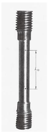
Firstly, Normal Strain $\epsilon$ is expressed as $\epsilon\,=\,\frac{L_0\,-\,L_f}{L_0}$, which $L_0$: Initial length of the specimen, $L_f$: final length of the specimen.
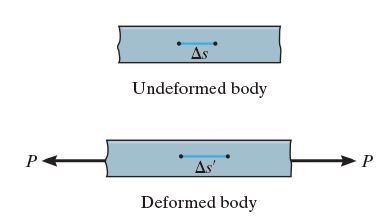
In a practical experiment like [Fig. 2] and [Fig.3], $\Delta s$ would be changed into $\Delta s’$ if the force P exerted on the body of specimen. In this case, the strain is expressed like $\epsilon\,=\,\underset{\Delta s \rightarrow 0}{\lim}\frac{\Delta s’\,=\,\Delta s}{\Delta s}$. Since the unit of numerator and denominator is the same, The strain is the non-dimensional value. Although the strain has no dimension, the unit of the strain is often expressed as [$\mu m/\mu m$]for convenience.
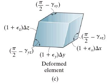
Secondly, Shear strain $\gamma$ is expressed as $\gamma \,=\,\frac{\pi}{2}-\theta$ for [Fig. 4].
What one can see in [Fig. 4] is, the normal strain is changed into
which makes a change of volume of the element. and the Shear strain is changed into
which makes a change in the shape of the element.
Then, what makes the stress and strain be bonded together? Hooke’s law is expressed mathematically by:
where $E$ is the constant of proportionality, which is called the modulus of elasticity or young’s modulus. Recall that $\epsilon\,=\,\frac{L_0 - L_f}{L_0}$. the Elongated Length or Gauge length of the specimen is $\delta$, and $\delta\,=\,\epsilon \times L_0$ so, $\sigma\,=\,E \epsilon\,=\,E\frac{\delta}{L_0}$, and it is converted into $\delta\,=\,\frac{P}{A}\times\,\frac{L_0}{E}$, means that elongated length of specimen is proportional to the Stress and Initial length. Let’s see the downward figures:
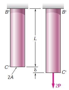
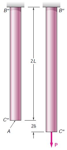
One can easily find that the elongation is proportional to the $P$ and $L$, and reciprocal to the $A$. Although these materials have all the same $E$ - it means that all of the specimen is composed of the same material -, in the composited material case one can see that the elongation is also reciprocal to $E$.
However, this linear elongation is not always seen. Before studying about why it is not always seen for any stress, let’s see the stress-strain diagram.
Likewise, the shear strain and stress have relation:
where $G$ is called the Shear modulus of elasticity or the modulus of rigidity. $E$ and $G$ has also relation like:
where $\nu$ is called the Poisson’s ratio of certain material, such that $\nu = -\frac{\epsilon {\text{lat}}}{\epsilon _{\text{long}}}$ where $\epsilon{\text{lat}}$: lateral elongation and $\epsilon _{\text{long}}$: radial strain(normally contraction).
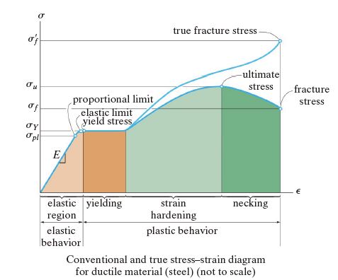
In Elastic Region, ductile material is elongated linearly, and it can be reversed - if the force is relieved in this region, the strain goes back. For [Fig. 7], in elastic region the slope is $E$ (Young’s Modulus).
In Yielding Region, the elongation occurs without increasing the stress. The stress that causes yielding is called the yield stress or yield point, $\sigma_Y$, and the deformation that occurs is called plastic deformation.
In Strain Hardening Region, any load causing an increase in stress will be supported by the specimen, resulting in a curve that rises continuously but becomes flatter until it reaches a maximum stress referred to as the ultimate stress, $\sigma_u$.
In Necking Region, its cross-sectional area will decrease in a fairly uniform manner over the specimen’s entire gage length. However, just after reaching the ultimate stress, the cross-sectional area will then begin to decrease in a localized region of the specimen, and so it is here where the stress begins to increase.
Until now, the relationship between the stress and the strain has been shown. Next, the ductility and brittleness will be shown, and by this we can obtain the knowledge about several forms of failures.
- References
- R.C. Hibbeler, “Mechanics of materials”, Pearson, 10th ed., ch.2 and ch.3
- Ferdinand P. Beer, Mechanics of Materials, 5th ed., ch.2